| Client | SBB |
| Architecture | Lorenz & Musso Architekten |
| General Planning | JV Aquatrain WGG Schnetzer Puskas Ingenieure (Lead) CSD Ingenieure |
| Planning | 1994-2009 |
| Realization | 2009-2013 |
| Status | Built |
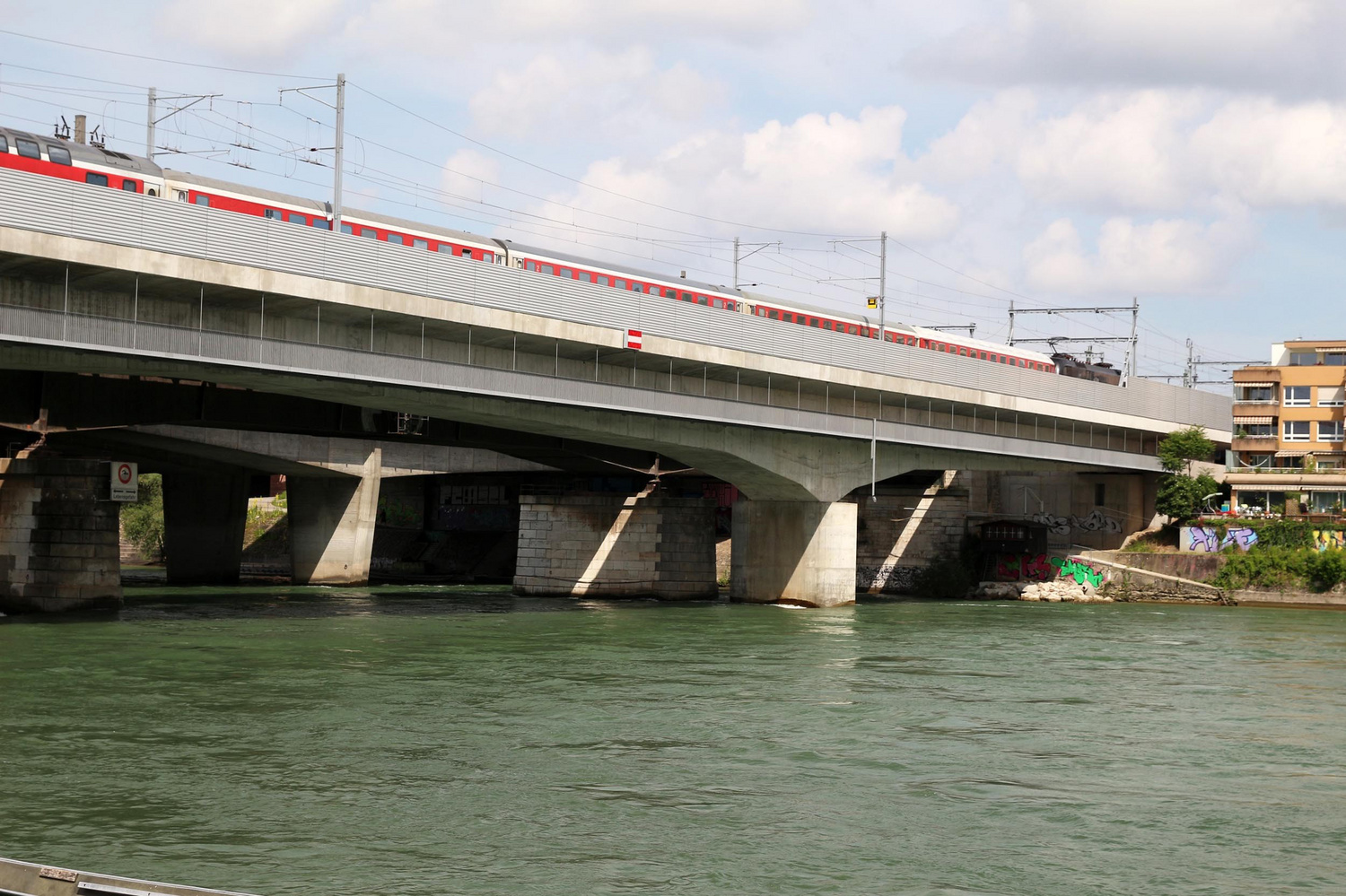
The commission for the SBB Rhine Bridge was selected as a result of a competition in 1994. The prescribed pillar locations and the maximum construction height were severe constraints. For these reasons, Schnetzer Puskas Ingenieure developed a prestressed reinforced concrete bridge. The static system is a cantilever bridge spanning three bays, whose spans are respectively 59.7, 117.2 and 59.7 m. The pillars are fixed in their superstructure and at their base and are subject to bending forces, due to traffic loading.
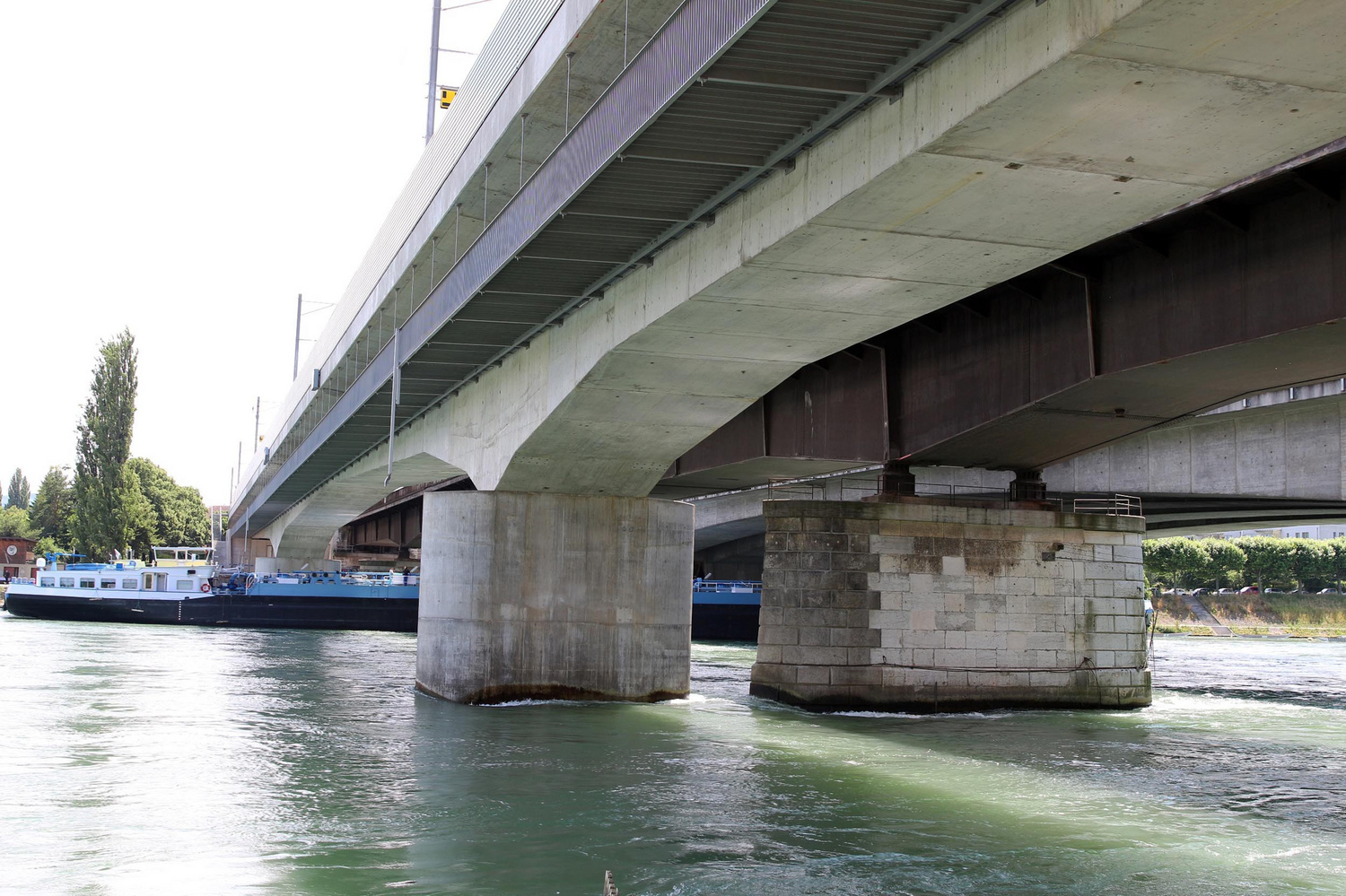
the frame system, which is being used for the first time for a large railway bridge, is advantageous for several reasons: The pillar walls have a much greater resistance to impact by ships due to the clamping system. The frame system is also more rigid, which is only made possible by a cantilever bridge with restricted construction height. In addition, no large and practically non-interchangeable bridge bearings are required.
A polygonal tapered beam laterally prestressed with a projecting carriageway on both sides is the main load-bearing element of the bridge construction. The shipping clearance gage limited the main span downwards - the end bays received the same symmetrical polygonal underside. The cross-section is 7.3 m over the pillars and 3.4 m high in the middle of the bay, and all load-bearing elements lie underneath the railway tracks. Cross beams transfer the forces via the abutments and river piers to the bearings and pillars. Additional cross beams transfer the deflection forces on the longitudinal axis of the bridge - which are due to the polygonal course of the lower pressure plate - to the walkways. The cross beam in the top of the bridge absorbs the deflection forces due to the kink in the lower box plate. The box girder in the abutment region was completely filled with concrete to a length of 4 m and its weight thus prevented the bearings from lifting. Prestressing the support consists - as usual in cantilever construction - of prestressing a cantilever arm and a bay. Continuity prestressing was also prescribed in the bridge box. It was prestressed externally and redirected over the cross beams, which favorably influenced the deformation behavior. The12.35 m high reinforced concrete pillars are angled - as is also the neighboring Schwarzwald bridge built by Ernst and Albert Schmidt - at 4 degrees to the current direction in the river. They were fixed in the 2.5 to 3 m thick and 9.2 by 13.3 m pile cap, which in turn transfers the load to four foundation shafts.
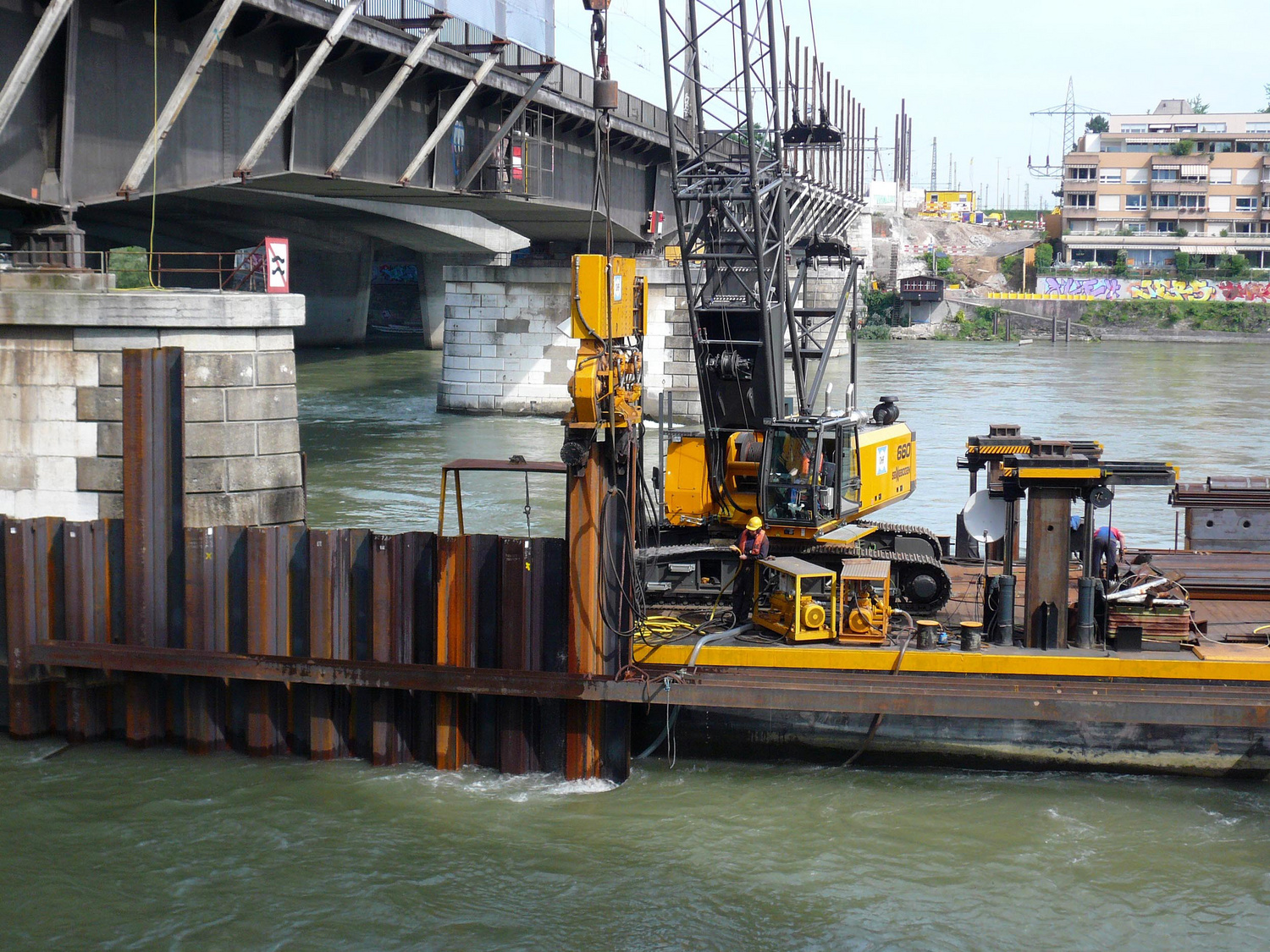
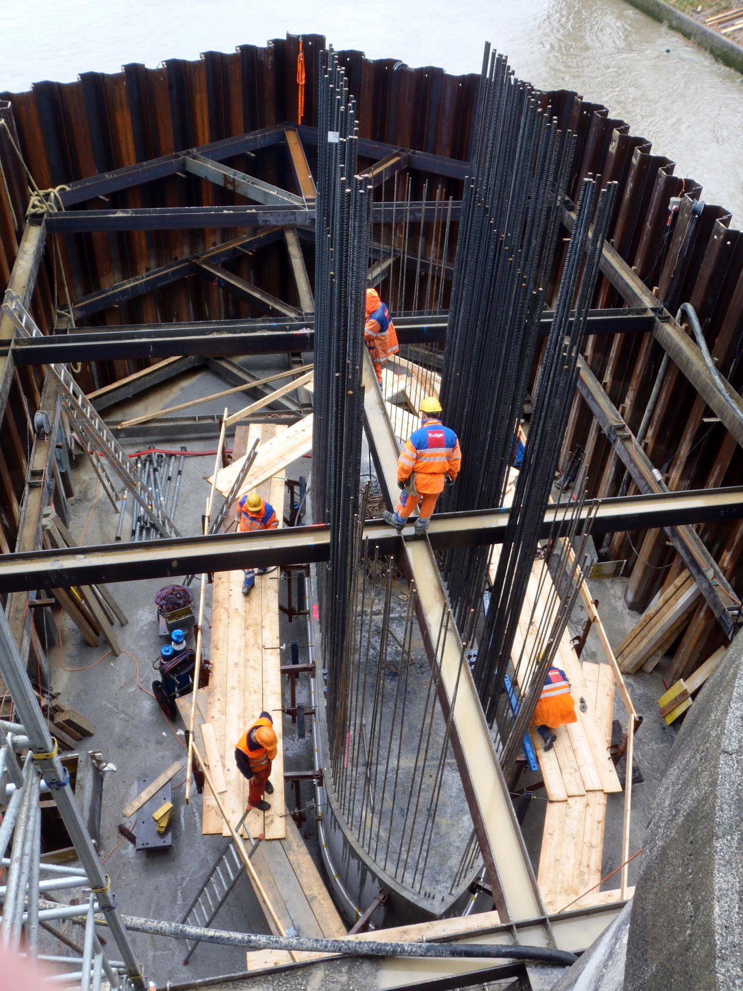
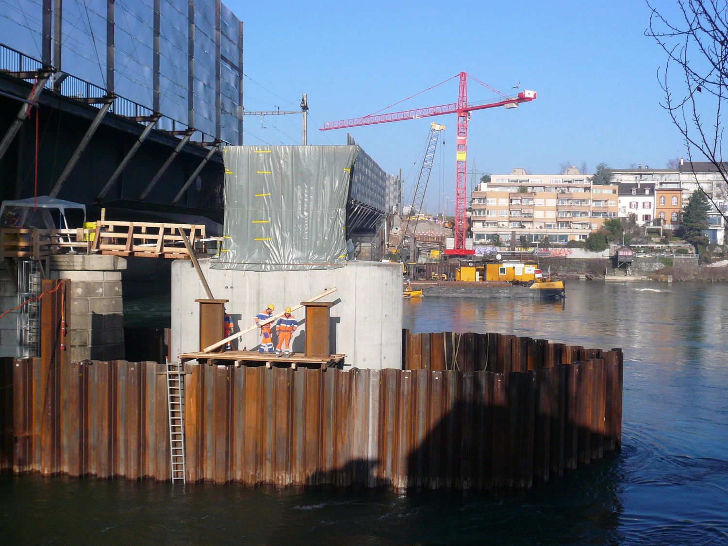
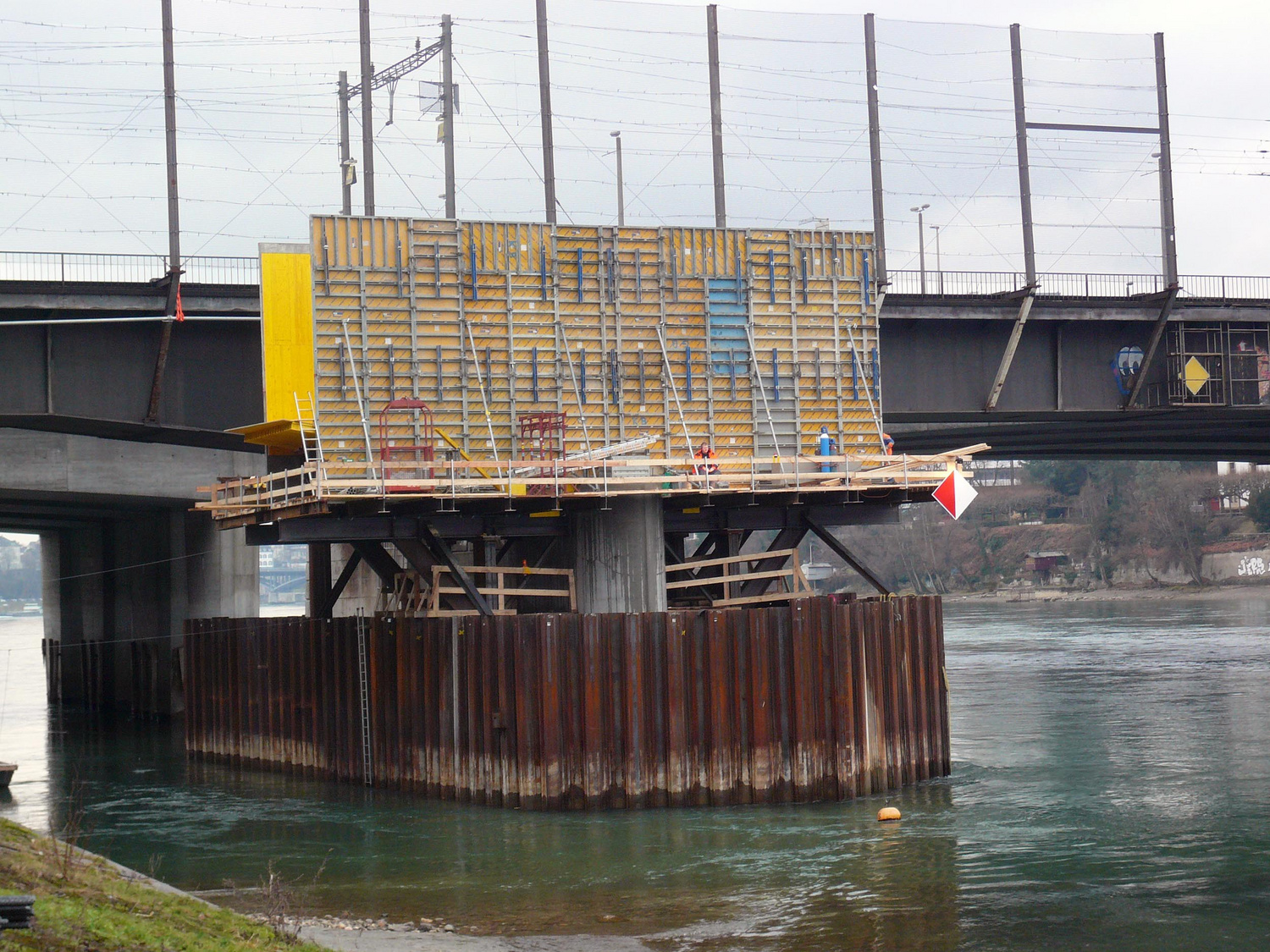
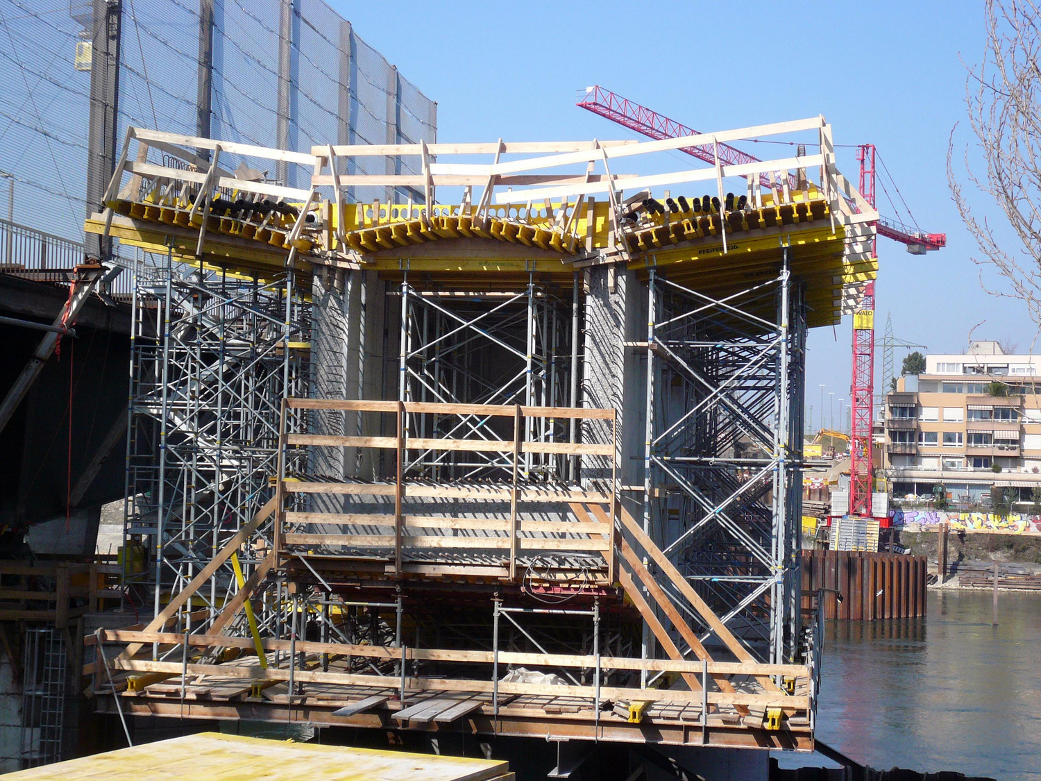
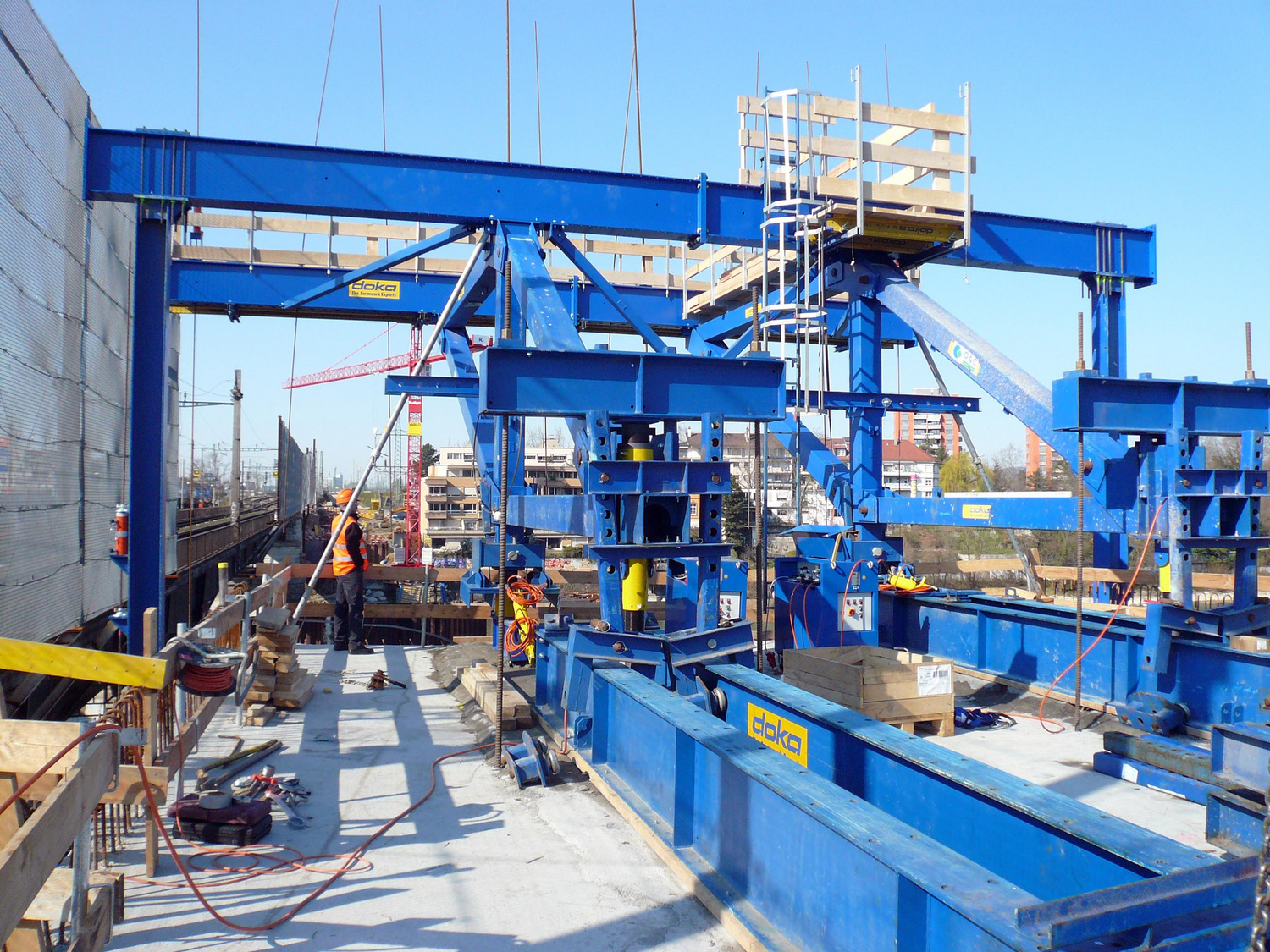
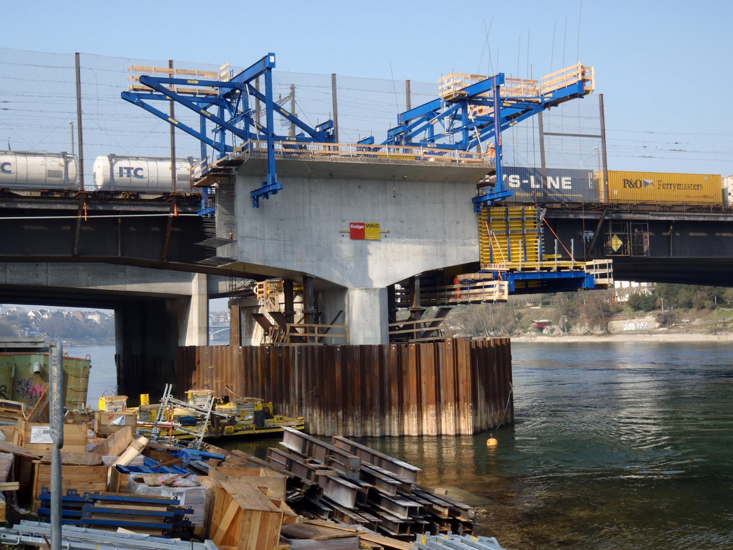
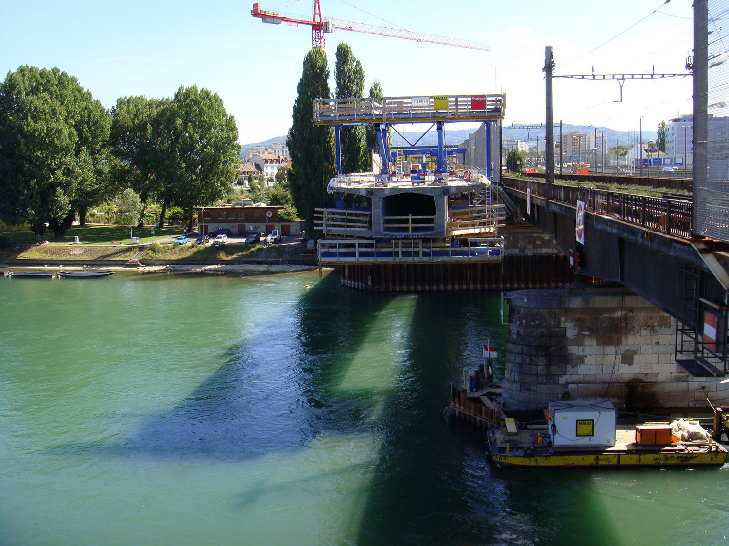
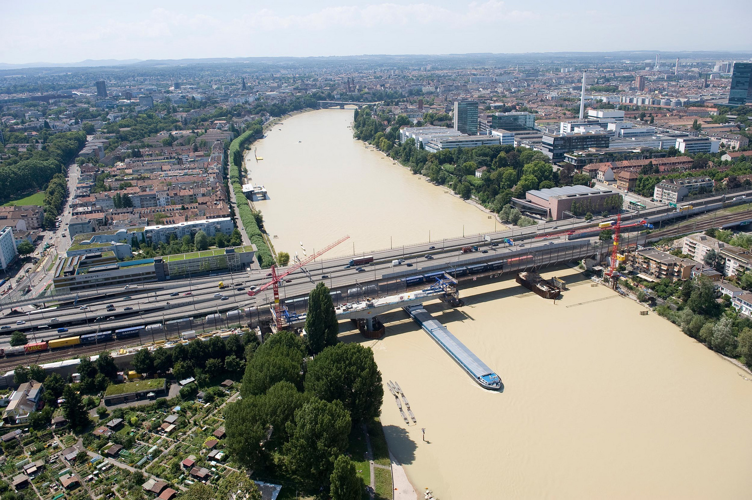
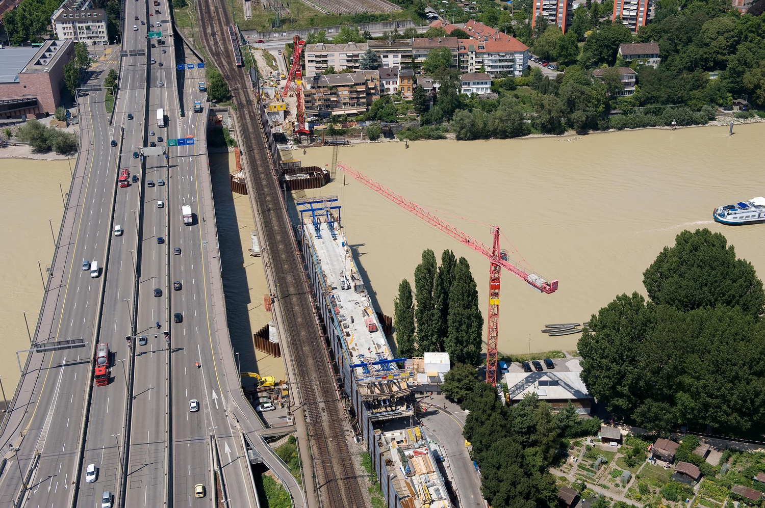
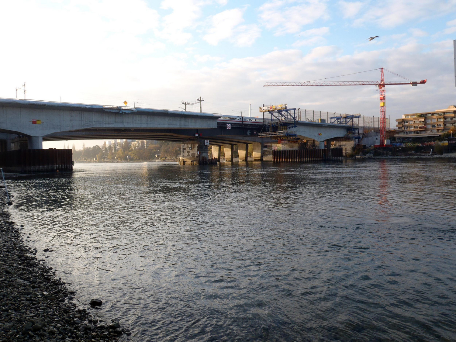
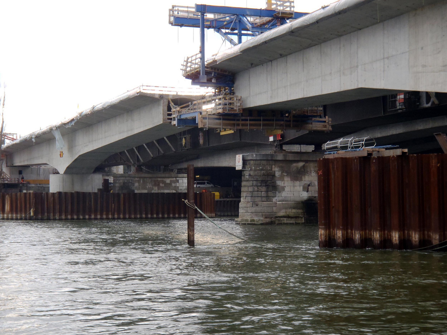
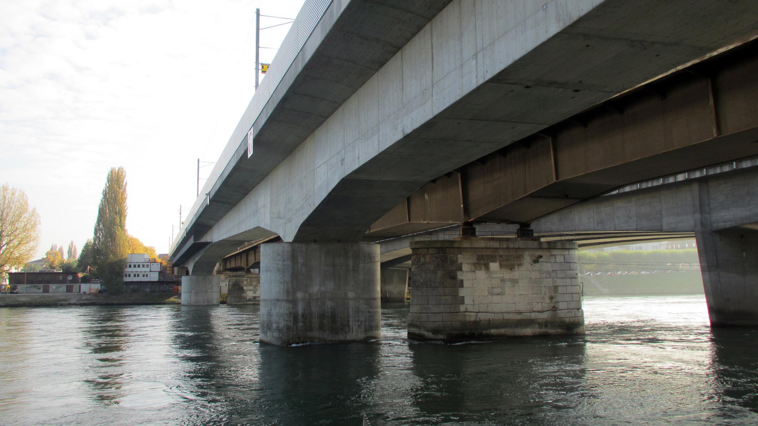
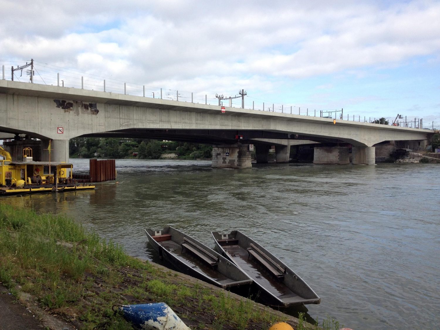
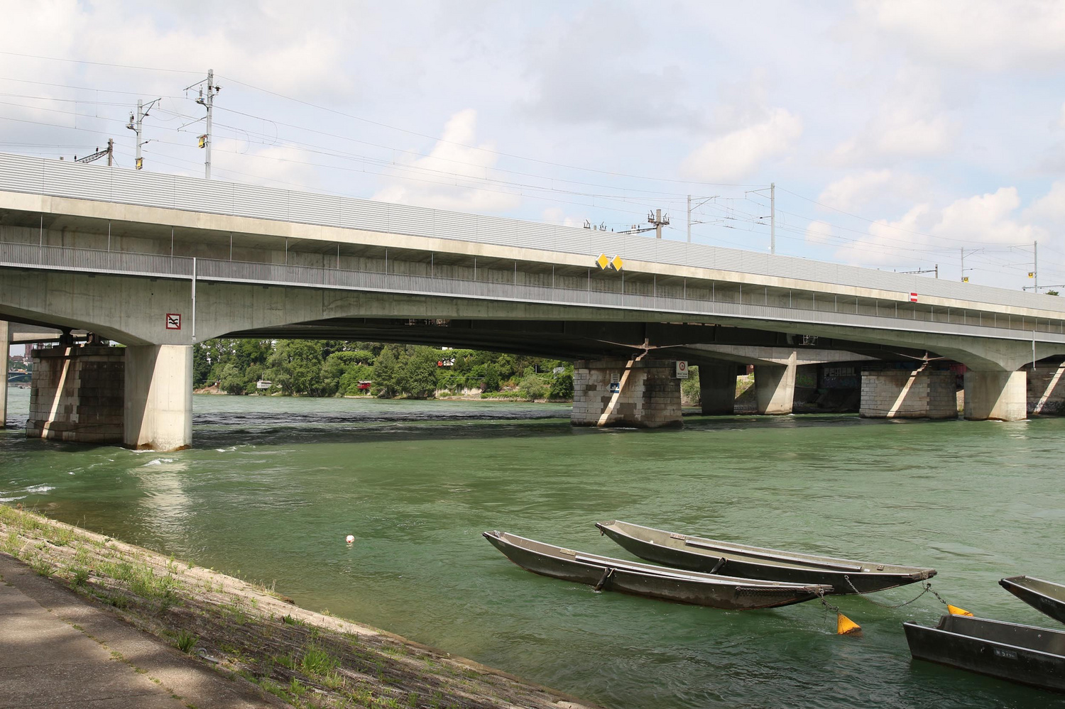
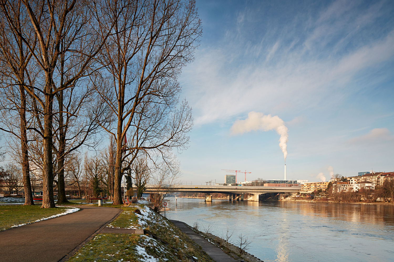 Foto-Werk, Michael Fritschi
 Schnetzer Puskas Ingenieure
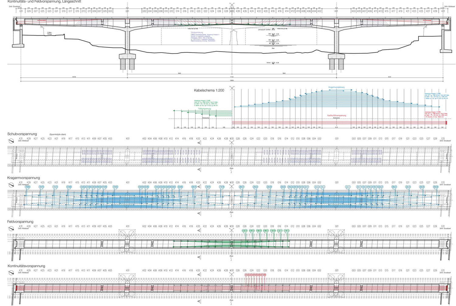 Top: longitudinal section with shear prestressing (violet), continuity prestressing (red), and division into cantilever construction stages; middle: prestressing concept; below: plan with anchorage points for the shear prestressing (violet), plan of the tendon layout for the cantilever prestressing (bleu), horizontal sections through bridge girder with mid-span prestressing (green), and with continuity prestressing (red)
Schnetzer Puskas Ingenieure
Top: longitudinal section with shear prestressing (violet), continuity prestressing (red), and division into cantilever construction stages; middle: prestressing concept; below: plan with anchorage points for the shear prestressing (violet), plan of the tendon layout for the cantilever prestressing (bleu), horizontal sections through bridge girder with mid-span prestressing (green), and with continuity prestressing (red)
Schnetzer Puskas Ingenieure
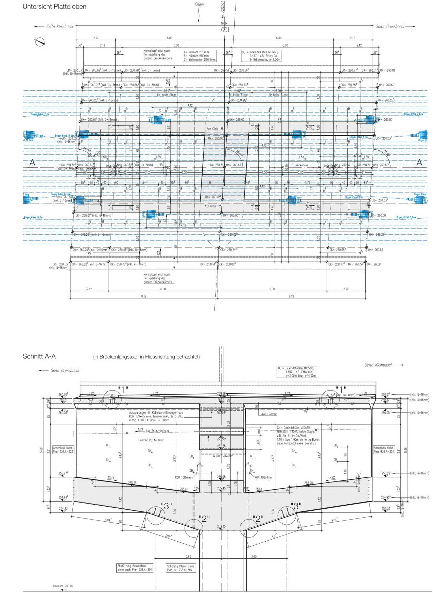 Top: horizontal section of the initial stage with tendon geometry and anchorages for the cantilever prestressing; below: longitudinal section of the initial stage
Schnetzer Puskas Ingenieure
Top: horizontal section of the initial stage with tendon geometry and anchorages for the cantilever prestressing; below: longitudinal section of the initial stage
Schnetzer Puskas Ingenieure
 Schnetzer Puskas Ingenieure
| Client | SBB |
| Architecture | Lorenz & Musso Architekten |
| General Planning | JV Aquatrain WGG Schnetzer Puskas Ingenieure (Lead) CSD Ingenieure |
| Planning | 1994-2009 |
| Realization | 2009-2013 |
| Status | Built |